 Sándor Ambrus
|
|
|
|
|
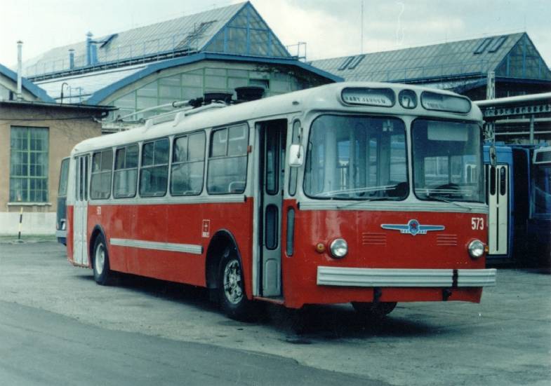
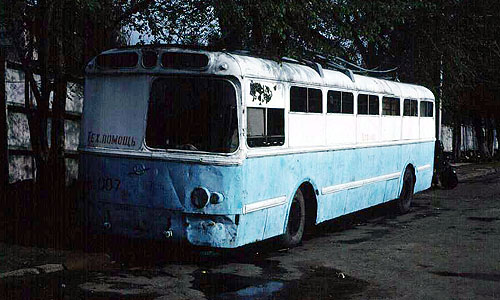
The ZIU-5 trolleybus |
|
|
Sándor Ambrus
|
|
|
The ZIU-5 type trolleybus was after the MTB-82
series the next, which was bought from the Sowiet Union. As the MTB 82
became a standard type in Budapest (since the
IK-60T was built after the plans of
the MTBs); the ZIU-5 also became a basic type of tht BKV (Budapest
Transportation Company). Here also not the very construction was basic,
but it was the first of a family, which had similar electric equipment
- the ZIU-9 and the IK-280.T1 (100 series) are very similar electrically to
the ZIU-5.
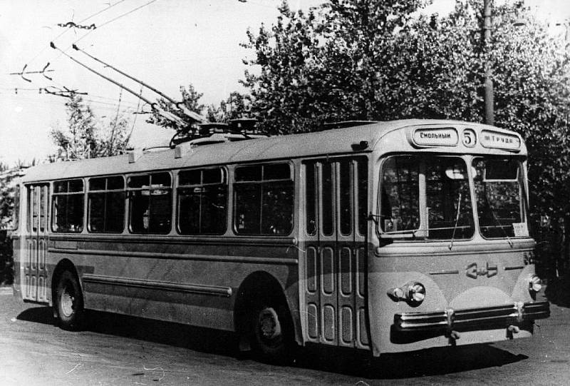
| The prototype of the ZIU-5 trolleybus and the ZIU-6 autobus - which
had similar body - were made in 1959. From 1961 the Uritsky factory in
the city of Engels started the mass production of ZIU-5, on average annually
200 vehicles were made.
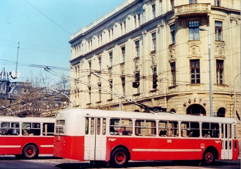
The first 7 pieces of ZIU-5 trolleybuses were put into service by the FVV (Capitol Tramways) in Budapest on 6th August 1966. These cars started their run on line 76. |
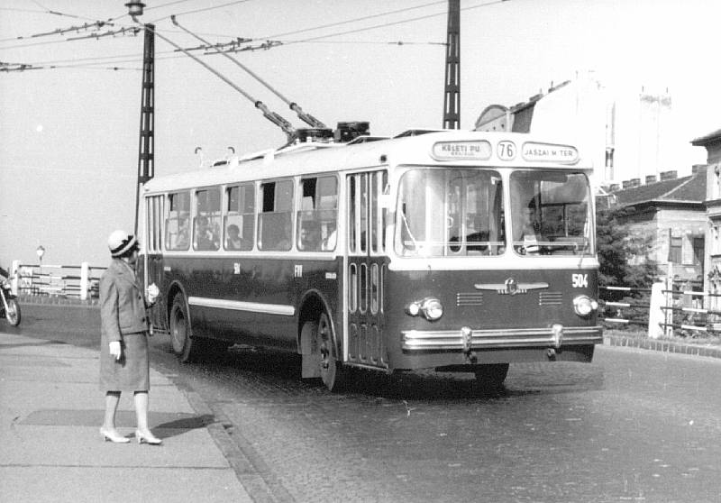 The new 504 trolleybus on Élmunkás híd (overpass) |
|||||||||||||||
| 100 pieces of ZIU-5 trolleybus was bought alltogether by Budapest,
between 1966-69. These obtained the numbers 500-599.
The supply of the ZIU-5s:
The ZIU-5 was longer than the earlier trolleybuses, on this type the servo help of the steering and the automatic regulation of the acceleration were also introduced. |
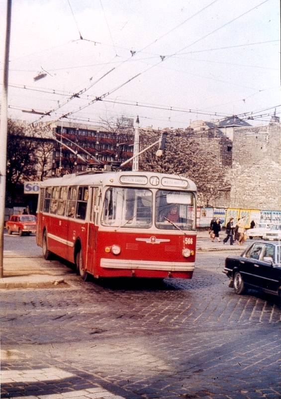
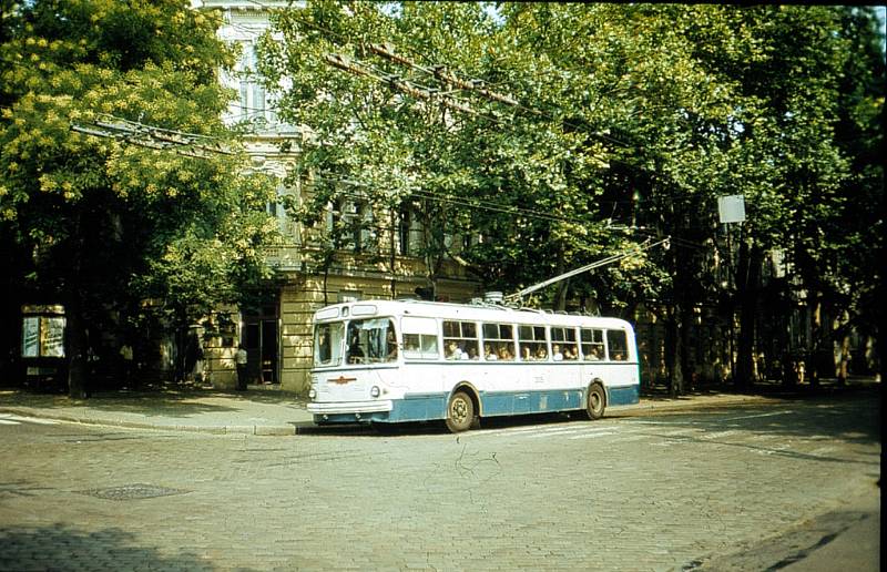
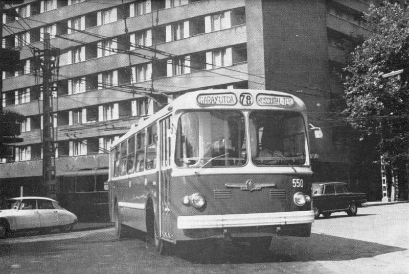 The trolleybus 550 around 1970. at the corner of Bajza utca - Damjanich utca (street). |
|||||||||||||||
| The ZIU-5 trolleybuses had only two side doors, so despite their
large room, the vehicles were not really suitable to the city-centre
traffic of Budapest. A further problem was, that the driver's cabin was
not well designed: since there was no window before the first
door, the door of the cabin and the first door together blocked the view
to the right. That is why between 1971-75 the BKV reconstructed the
front door: instead of the original four wings they replaced to three
wings, and a window was made before the door. This worsened the speed of
the passenger exchange at the stops.
The ZIU-5 did not last long, the scrapping of the first two was in 1975. The electric equipments of the vehicles scrapped until 1978 were moved to Ikarus bodies: e.g. the 100 IK-280 articulated and the 600 IK-260 solo car obtained the equipment of the first stalled two. This was the birth of the 100 series of articulated trolleybuses in Budapest. |
 Sándor Ambrus |
|||||||||||||||
| The building of the Ikarus trolleybuses lasted until 1978: alltogether
79+1 new trolleybuses were made (possibly spare electric units were also
used above the scrapped ZIU-5s).
Scrapping of ZIU-5:
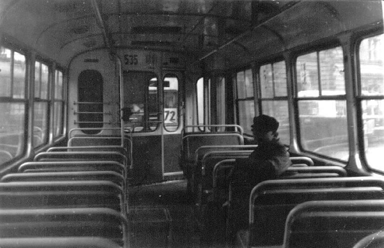
The last 23 trolleybuses were stalled in 1981-82. Last time they ran in line 72. By this time these trolleybuses were operating rather unreliable comparing to ZIU-9s, so the drivers of ZIU-5 obtained extra bonus for the many lost courses because of technical failures. |
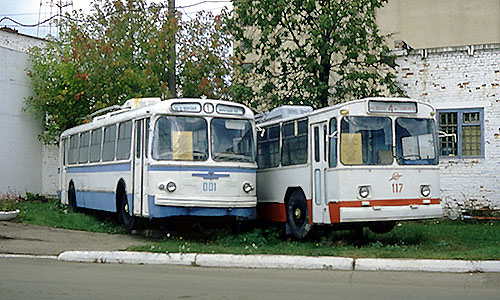
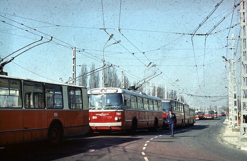 The trolleybus 598 in the queue in front of Pongrác depot. Behind is the successor: one of the 100 series articulated trolleybuses |
 |
 |
|
|
|
 Sándor Ambrus
|
 |
|
|
|
|
|
|
|
|
|
|
|
|
|
|
|
|
|
|
|
|
|
|
|
|
|
|
|
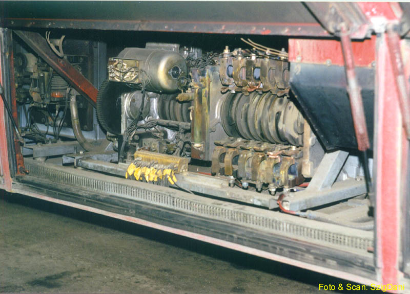
The electric circuit of the ZIU-5 is in many aspect the automatic version of the MTB-82's equippment. Both types have double coiled motors: with a main circuit (serially coupled to the rotating part) and a separate outer exciting circuit. Also the principle of the coupling is similar, both in acceleration and rheostatic brake. The main difference is, that there are less contactors in the ZIU-5, because the varying of the resistors are mainly done by the automatic starter device.
This brought some other changes, mainly because the starter
works only "one way": it is not able to reopen the electric circuit.
|
On the image is the starter of one of the IK-280 trolleybuses in Debercen (401-404), which is fitted with ZIU-9 equippment. The starter of the ZIU-5 was almost like this: on the left there is the motor, on its right the cylinder and the coupling elements are visible. |
 Dániel Szigeti
|
Since the starter cannot get the resistors out of the circut, there
are contactors to do so. The manouvre contactor LK3 can insert a large
resistor in the main circuit and the line contactors LK1 and LK2
shut the main circuit completely out of the poles. At the end of the
acceleration
there is this two step of closing the circuit before the accelerator
turns back the cylinder into the initial position.
At the beginning of the acceleration this happens opposite way:
first the line contactors turn on the motor, then the LK3 gets out of
the circuit the large resistor in less then a second. This is the manouvre
stage: it is possible to go like this (with all the resistor coupled by
the starter inside the main circuit) in low speed.
|
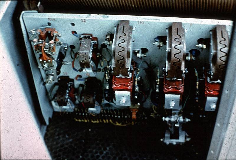
The LK1 line- , T brake-, LK3 maneuvre contactors; the S2, S3 exciting circuit contactors, and the KDK compressor regulating contactor are visible. Also there are some relays: the zero voltage relay (RN), the maximal relay (RT) and the acceleration relay (RU) is there. The rest is covered by the wall of the driver's cabin. |
 |
The speed of the starter is regulated by the acceleration relay (RU), which stops the cylinder if the current is higher than a certain threshold. This threshold is 250 A in the second position of the accelerator pedal, and it is lower at the first position. In case there are some irregularities in the level of the current, first the maximal relay, then the fuse switch (which is above the head of the driver) can break off the circuit.
At the end of the acceleration, the R accelerator contactor short
circuits all the resistors (and also with this the outer excitation is decreased).
This happens around the speed of 30 km/h. After the shunt
cascades come into the play, regulated also by the starter. Hereafter
the speed of 60-80 km/h was possible to reach. There is three shunt
possibility according to the accelerator pedal position.
The acceleration of the ZIUs are not very smooth: the beginning of the starter's operation, the coupling of the R contactors and the shunt cascades make a considerable kick to the car. However the articulated 100 series with ZIU equippment were much better: the larger weight of these trolleybuses nicely decreased the strength of these kicks, without considerably loosing the speed and accelerating power.
There is no possibility of recuperating brake on the ZIUs, since the
shunts are regulated also with the starter. For decreasing the speed there is the
rheostatic brake.
By pressing the brake pedal all the main circuit will be out of
voltage
by releasing the line contactors (so during the brake the starter can go
back). However the brake contactor T makes the rotating part coupled
on the resistor of the LK3 (which is also released). The S
exciting-circuit contactors regulate the current of the braking in two stage:
this gives a very smooth and not exremely powerful decrease of speed.
During the brake pedal is pressed, the trolleybus uses a small current
to supply the exciting magnets: if there is a dead section (e.g. tram
crossing), then the rheostatic brake becomes ineffective. By pressing
the pedal further down, the pressure air brake could always fully stop
the vehicle.
|
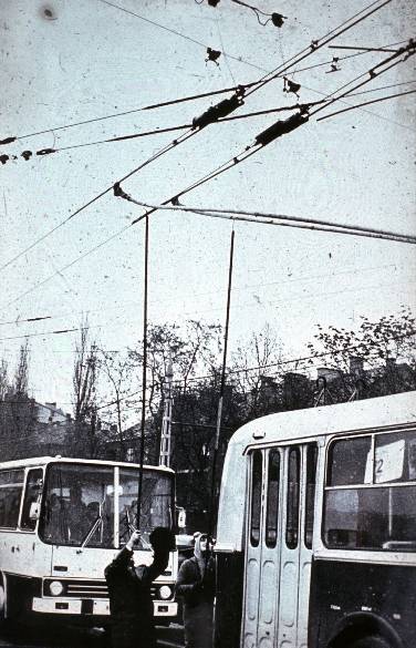
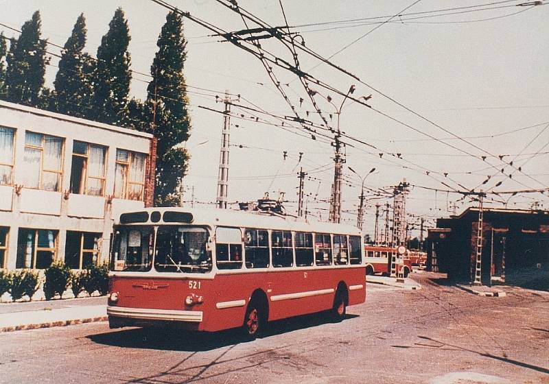
The ZIU-5 had the old iron trolleys; if it got loose it could make more serious damage as todays' aluminum trolleys. Also the older trolleys were just painted, but had no insulating cover: so the side of the trolley could cause an electric shortcut stalling in the overhead wire-system. |
 |
|
On the picture is the 521 at the entry of Pongrác depot, in the '70s. The radio-filters are visible on the roof: to the 600 V trolley belonged twice as large as to the 0 V. These were made of coils and capacitors. |
 |
Electric devices operating from accumulator:
The ZIU-5 had interestingly two low-voltage circuit: 12 V and 24 V. The microphone (installed posteriorly), the turn signals, the front lights, the speedometer and the windscreen wiper operated from 12 V, the rest from 24 V. The 24 V circuit was joint to a dynamo (with own motor running constantly) to charge the accumulator, the 12 V was probably simply branching from the accumulator cells. Later the 12 V devices were using 24 V with a resistor in the circuit.
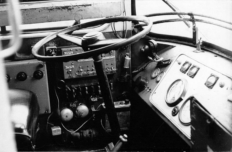
Let's have a look in the driver's cabin:
 Rudolf Lakos
|
 |
|
Heating switch (F), 17 low-voltage switches (K), windscreen wiper (A), 9 low-voltage fuse (b), emergency- and no-voltage bells (cs), amplifier (e). Behind the heating switches was the switch of the dynamo. These parts are better hidden on ZIU-9. |
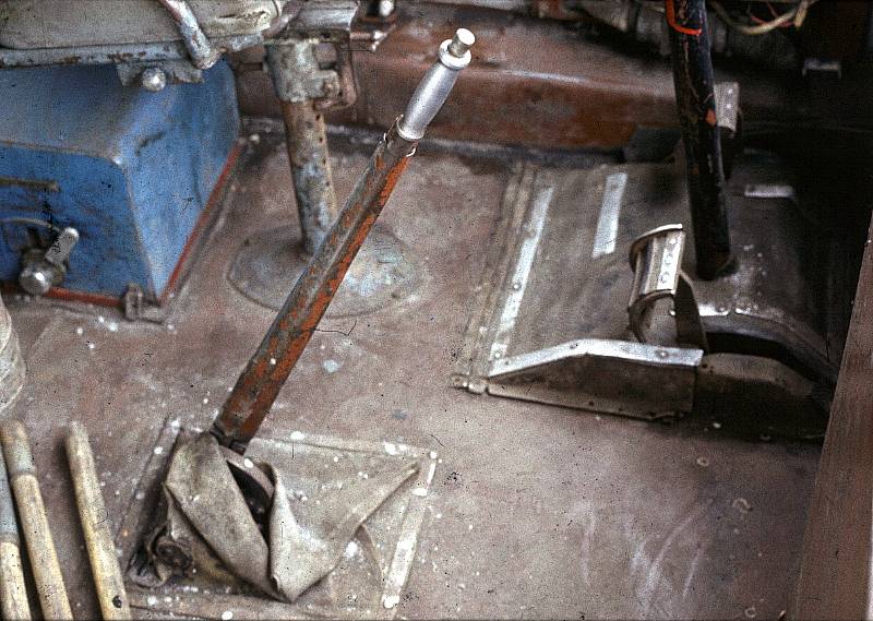
direction selecter (Iv), handbrake (Kf), accelerator (M), brake (F). The box of the direction selecter contains the also the KVP-22 type controlling cylinder: this is mechanically joint to the pedals. The arm of the direction selecter was removeable, this was supposed to be taken by the driver. |
The doors ran with 24 V motors. The switches of the doors
had three stages: in the middle stage it was possible to turn off the
motor. This was neccessary when the door was shutting someone: the
motors could quite heavily press the passenger, and if the doors did not
go to the end, the motor could burn down.
A get off requesting signal was only at the rear door.
 |
 Rudolf Lakos
|
|
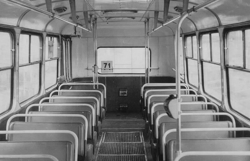
The cover of the seats was typical russian: the soft coushioning compensated the hard suspension of the trolleybus. It was a usual view as the passengers bounced together on the seats as the vehicle went through a bump on the road. At the back was the conductor's seat, which was never used in Budapest, since by the time the trolleybuses went into the service, there was no conductor job. |
|
 |
 Ferenc Szántó
|
|
|
|
 Blickpunkt Strassenbahn
|
 Blickpunkt Strassenbahn
|
|
|
|